
In order to use our 2024 OEM Navigation Map Updates, you need to install our Maps Converter software from the supplied USB memory stick
Average time to install: 10 minutes
Items supplied in this kit are:
| Maps Converter Software on USB Memory Stick |
2024 Map Update SD-Card |
 |
 |
All work in this installation takes place inside the car and involves software running from the supplied USB memory stick and replacement of the existing OEM Navigation SD Card.
Map Chooser Software Install
To install the Maps Converter software, the software needs to be loaded via the car's entertainment unit:
a. Turn ON the car's ignition ON (DO NOT press the clutch / brake pedal and do NOT start the car)
b. Insert the supplied USB memory stick into one of the two USB ports in the center console (under the entertainment system)

c. The software will start running on it's own. You will then be presented with a number of screens, some with choices, as shown below:
 |
d. Click YES - GO ON to continue installation. You will then see the following screens:
 |
 |
d. Click on FIAT to use Fiat (original) map updates; or click MAZDA to use our new 2024 map updates. PLEASE ENSURE YOU PICK MAZDA AT THIS STAGE.
e. The Maps Converter software will now switch the car to using MAZDA maps. Please be patient - this process takes a few minutes to complete.
 |
f. Once the Map Conversion has completed, you will see the screen below. Please remove your existing Maps SD Card and insert the one supplied at this time.
 |
g. Finally you will see some more screens informing you that the Map Conversion has completed. Please remove the USB memory stick when instructed and wait for the car's entertainment system to reboot.
You should now be able to use the latest Mazda Map SD-Card. Please open the Navigation application to ensure the system loads correctly.
The Sequential LED Front Indicators are installed in both the left and right hand sides of the front bumper, which is accessed via the front wheel arches. The existing wiring is not altered in any way - the new wiring being plug and play with existing connectors.
Average time to install: 2 hours
| Left Indicator Unit |
Right Indicator Unit |
 |
 |
| Wiring Loom x2 |
Piggy-back wire taps x2 |
 |
 |
There are 3 main parts to the Sequential LED Front Indicator installation. These can be broken down into:
 |
 |
 |
 |
 |
 |
 |
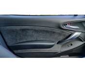
The alcantara door card inserts are installed on your existing door cards and involve their removal, modification & refitting.
Average time to install: 4 hours
Items supplied in this kit are:
| Alcantara Door Card Inserts |
 |
There are 3 main parts to the Alcantara Door Card Inserts installation. These can be broken down into:
(as both doors are the same, only one side will be shown in the instructions below)
1. Removal of the door cards (both left hand (LH) and right hand (RH)
2. Modification of the door cards, including fitting the Alcantara inserts
3. Refitting the door cards to the car
1. Removal of the door cards
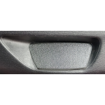
a. Remove the silver door pull insert. This is quite stiff and needs to be pried up from the bottom towards the top, taking care not to damage the surrounding plastic.
b. Remove the smooth plastic trim piece from behind the door handle - the easiest way to do this is to pull it off (gently) from the door hinge end of the door by putting your fingers behind the panel and pulling outwards.
c. Remove the 1x philips / posidrive screw which was concealed by the door handle trim. Remove the 2x philips / posidrive screws holding the door pull in place. Do not try to pull the door pull itself off the door.
 |
 |
 |
d. Starting at the bottom middle, pull out the 8 puh clips holding the lower edge and both sides of the door card in place. Use your fingers to reach between the rubber door seal and the edge of the plastic door card and pull gently outwards. Do not use too much force.
e. Lift the door card upwards to release it from the door. Be careful to NOT move the door card too far away from the door as it is still connected by wiring and cables.
f. The door handle and it's associated cables will likely ping out of the door card whilst you're holding it - this is absolutely fine and is to be expected. If they don't release on their own, grab the interior door handle end of the two cables and pull them gently away from the door card, angling towards the front of the door. The mechanism will the unclip from the door card.
g. Finally unplug the two multi-plug connectors (drivers door) or one multi-plug connector (passenger door) going to the window switch pack in the door card.
2. Modification of the door cards, including fitting the Alcantara inserts
a. Use a flat head screwdriver, or other suitable implement, to push in the clip holding the upper part of the door pull to the rest of the door card
b. Placing one door card on a suitable flat & clean surface, remove the 24 philips-type screws circled below. This will help in seperating the three parts of the door.

c. To allow the parts of the door card to be fully removed, we need to drill or cut two plastic-welded plugs at the lower part of the door card (circled). You may find gentle use of a large drill bit is the easiest way to do this - you can clean up any rough edges afterwards (we will not be replacing these connectors as they are not needed). In the picture below these two plugs have already been drilled and cleaned up aftwerwards.
d. It is now necessary to remove the window switches and their surrounding panel. This is easiest if you remove the switches first by unclipping the four plastic lug-type clips holding each switch body the the door card panel and then removing downwards (away from the face of the switch). Next, the metal clips holding the switch surround to the door card panels need to be removed. These clips are strong and awkward to get at initially, but use patience and small flathead screwdrivers to gently push them out. The window switch surrounds will prevent splitting the door card apart below, so take time and care over this step.
e. You should now be able to seperate the three parts of the door card. The bottom section needs to be twisted slightly to allow the plugs drilled out above to seperate properly from the middle part of the door card. Place the top and bottom sections aside as we only need to concentrate on the middle door card section.
f. Use a flat head screwdriver, or similar, to push out the 5 clips holding the armrest to the middle door card section. You should now have a middle door card section which looks as below:
g. Taking care to ensue you have the correct side, lay the alcantara fabric on top of the middle door card section. Each alcantara panel is cut slightly over-size, so you may need to trim it slightly to fit your door card. This is done to allow for small inaccuracies in measurements or placement of the alcantara.
h. Using the lower doorpull hole and cutouts for the armrest to allign the alcantara panel, ensure there is sufficient fabric to cover all the existing vynl. Refit the armrest to help hold the alcantara panel in place whilst you check and align it fully.
i. The next step is to glue the alcantara panel to the door card. Make sure the door card vynl is completely clean and free from any contaminents (grease etc.) We recommend using a spray contact fabric adhesive and gluing the panel in 2 parts - this way you can hold the panel in place with the armrest; glue to top part of the alcantara panel, then, when that is dry (allow at least 30 minutes), remove the armrest and glue the lower part of the alcantara panel.
Items to note whilst doing this:
i. You need to ensure that the returns on the back-side of the door panel part are glued along with the alcantara - this is essential to ensure the alcantara sticks to all parts of the vynl.
ii. Practice stretching the alcantara round the tight cornersat the top of the door panel so you are certain how these will glue.
iii. You need to be very careful not to get glue where it is not wanted.
iv. When glueing the lower part of the alcantara to the door panel, great care is needed to avoid any creases being left in the alcantara.
v. Most contact glues give you only one chance to get the glueing right - please take car, and if you're not sure, take a break and practice with waste material such as waste paper.
j. With all the glueing complete, leave the panel on a flat, clean surface for at least 2 hours to allow the glue to fully cure.
k. Finally we need to re-assemble the 3 parts of the door card, in the reverse of how we removed them. You need to fit all three parts together before the screws can be put back in, but you might find it useful to try fitting the upper and lower edge screws to help keep everything together whilst you screw in the others.
3. Refitting the doorcards to the car
a. Refitting the door cards is the reversal of removal. Firstly plug the multi-plug connectors for the windows back in to their relevant sockets.
b. Re-hang the door cards onto the door by placing the top of the door card above the top of the door metl and pushing down gently. Push in the plastic push rivets around the door sides and bottom, and then re-insert the three screws holding the door panel in place.
c. Finally, replace the two trim pieces you removed from the door card at the beginning.
Your installation is now complete.
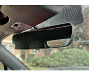
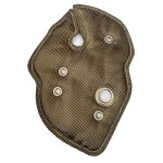
The airbag warning panel replacement is installed in place of the existing warning panel. It is accessed by dismantling some of the lower dash panels.
Average time to install: 10 - 30 minutes
Items supplied in this kit are:
| Airbag warning panel replacement |
 |
All work in this installation takes place inside the car and involves items in the centre console. You will need a large philips type screwdriver, a small flat head screwdriver and a T10 Torx screwdriver.
Work in the Car
To fit the airbag warning panel replacement, we need to remove the airbag warning panel from the car and then replace the display screen within it.
a. Gently squeeze the outside edges of the trim piece surrounding the airbag warning panel and pull it forward towards you. There are clips on each side of the inside of the trim piece which will release, allowing you to fully remove the trim.
b. There are two screws holding the airbag warning panel into the car (one each side of the panel) - use the large philips screwdriver to remove these, which will then allow you to pull the airbag warning panel away from it's location in the car.
c. There is an electrical connector on the back right hand side of the airbag warning panel as you look at it. Pull the airbag warning panel away form the car and use the small flat head screwdriver to help release the clip holding the connector in. It may feel quite tight on the wiring, but there is sufficient spare wire to be able to release the connector without too much trouble, Once released, you will be able to fully remove the airbag warning panel.
d. There are two T10 Torx screws at the back of the airbag warning panel - use the T10 screwdriver to remove them.
e. Unclip the three clips on the bottom and three cips on the top of the airbag warning panel. This will allow the two halves of the panel to come apart, allowing access to the warning screen inside.
f. Use the small flat head screwdriver or your finger to help release the central clip holding the airbag panel into it's surround. It should release fairly easily.
g. Place the replacement airbag panel in the housing and ensure it sits tight against the front of the airbag panel cover. Push the panel so it clips into place.
h. Re-assemble the warning panel, making sure the six clips connect back together, and replace the two Torx screws.
i. Finally re-install the airbag warning panel in the car. Installation is the exact opposite of removal, consisting of re-connecting the electrical connector, screwing the airbag panel back into place, and finally replacing the trim surround. When installing the trim, make sure there are no bulges at the rear of the trim piece, as sometimes the clips can be pushed out wide under the lower dash. Keep your hands on each side of the trim piece whilst installing it to avoid this happening.
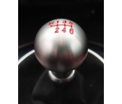
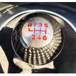
The wireless charger is fitted underneath the rubber part of the centre console shelf, in front of the gearstick.
Average time to install: 30 - 60 minutes
Items supplied in this kit are:
| Wireless charger coil |
USB cable |
 |
 |
| Car USB adaptor |
|
 |
All work in this installation takes place inside the car and involves items in the centre console. For best effect (to avoid any noticeable bumps under the rubber mat), it is advisable to modify one of the centre console panels using files, sanders etc. This is not completely necessary for the installation to work if you do not feel comfortable doing this.
Work in the Car
To fit the wireless charger, we first need to remove parts of the centre console trim. We will then optionally modify a hidden part of the trim; fit the wireless charging loop; install wiring; andf re-assemble the centre console.
a. Remove the gearlever knob by unscrewing in an anti-clockwise direction
b. Pull up on the silver part of the gearlever surround by gripping the inside edge of this part on each side, where the gearlever gator meets the surround. You have to pull relatively hard, but eventually the trim will release. If the front of the entertainment contol panel lifts up, merely push it down again whilst holding up the gearlever surround. When both clips are free, remove the surround panel by pulling gently up and backwards.
c. Turn this trim piece over and remove the rubber mat by uncliping the five rubber tangs securing it to the front of the gearlever surround. There is a piece of double sided tape holding the curved rear edge to the gearlever surround - gently pull the rubber away from this tape until it is completely removed.
d. If you are going to modify the centre console panels to allow for the best fit, it is necessary to remove the front plastic panel from the gearlever surround. This is held on by two plastic (white) clips - gently pry first one side then the other apart until you have the front piece seperated from the gearlever surround.

e. Using a Dremel or similar device, remove some of the plastic on this front panel piece so that it somewhat resembles the picture below. You do not need to remove quite as much material as shown in this test piece; you are merely trying to create the 3 or 4 mm clearance needed between the plastic base (the piece you are modifying) and the rubber mat which sits on top of it
f. If you are not happy modifying this panel (as shown below); you can sfely ignore these steps and proceed to the next step.
g.  Re-connect the two panals which we previously disassembled, so that they look something like the picture to the right. This is the last step of bodywork modification.
h. We now need to install the wireless charging coil on top of the front plastic panel, ensuring that the coil is clear of the forward central rectangular hole in this panel (which is where one of the rubber mat's clips fits). Place the coil in place and ensure it clears this hole, as indicated below. 

i. Once the coil is in place, secure it with a piece of double sided tape below it; then refit the rubber mat over the top of the plastic. Ensure the wires from the coil pass either side of the rubber mat's middle fixing, and then do up the rest of the rubber clips. Finally attach the circuuit board to the underside of the whole assembly.
j. The coil is now fitted to the centre console panel, so all that remains is to run a USB power cable from the centre console to the closest power source. This can be accomplished in a variety of ways, but I chose to route the cable under the centre console front trim so that it exits in the passenger side footwell next to the car's built in auxilery power socket (cigarette lighter socket). I then plugged a car socket to USB converter into this socket to provide the needed USB power connection.
k. Finally, re-install the centre console shelf into the car, ensuring you plug in the USB cable at both ends, then turn the ignition on and check that your phone starts charging as expected.
If you have any problems with this installation, please see our FAQ articles relating to it.
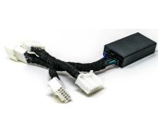
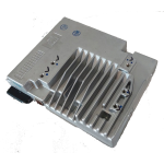
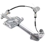
[UPDATED] The window controller V2 is installed within the drivers side door, behind the door card. The unit is self contained and doesn't require any modifications to existing parts or wiring
Average time to install: 30 minutes
Items supplied in this kit are:
| Window controller box |
Window switch loom |
 |
 |
| Remote control loom |
|
 |
All work in this installation takes place inside the car and involves fitting items within the drivers side door. No wiring or component modifications are necessary for this installation.
Work in the Car
To fit the window controler v2, we first need to remove the drivers door card, whcih is the plastic internal facing of the door.
a. Remove the silver door pull insert. This is quite stiff and needs to be pried up from the bottom towards the top, taking care not to damage the surrounding plastic.
b. Remove the smooth plastic trim piece from behind the door handle - the easiest way to do this is to pull it off (gently) from the door hinge end of the door by putting your fingers behind the panel and pulling outwards.
c. Remove the 1x philips / posidrive screw which was concealed by the door handle trim. Remove the 2x philips / posidrive screws holding the door pull in place. Do not try to pull the door pull itself off the door.
|
|
|
d. Starting at the bottom middle, pull out the 8 puh clips holding the lower edge and both sides of the door card in place. Use your fingers to reach between the rubber door seal and the edge of the plastic door card and pull gently outwards. Do not use too much force.
e. Lift the door card upwards to release it from the door. Be careful to NOT move the door card too far away from the door as it is still connected by wiring and cables.
f. The door handle and it's associated cables will likely ping out of the door card whilst you're holding it - this is absolutely fine and is to be expected. If they don't release on their own, grab the interior door handle end of the two cables and pull them gently away from the door card, angling towards the front of the door. The mechanism will the unclip from the door card.
g. Finally unplug the two multi-plug connectors going to the window switch pack in the door card. Now place the door card aside, being careful not to scratch or damage it.
h. Plug the black multiplug of the window switch loom into the window controller box and then plug the two white multiplugs on that loom into the window switch pack in the door card. Use the supplied sticky-back velcro strip to stick the window controller box to the inside of the door card.
i. Unplug the white multiplug connector from the door body (it may help to release the clip holding the plug in place if you press it with a small screwdriver). Now tap into the GREEN and YELLOW wires on this plug using the wiretap connectors on the remote control loom. The RED wire of the remote control loom needs to connect to the GREEN wire on the multiplug connector; and the BLACK wire of the remote control loom needs to connect to the YELLOW wire on the multiplug connector; as shown below. When the wires have been connected, plug the multiplug connector back in to the socket in the door.
j. Route the long part of the remote control loom (with the two pin plug attached) along the existing door wiring towards where the window swtich plugs are dangling from the door.
k. All the wiring installation is now complete. The last step is to reconnect the door's window plugs and the new remote loom plug into their respective sockets in the window switch loom. Each plug can only go in one socket and can only go one way around.
l. Finally re-hand the door card onto the door by placing the top of the door card above the top of the door metl and pushing down gently. Do NOT fully re-attach the door card until we have tested everything works correctly.
m. You may find it easier to close the drivers door from the outside and then get in the passenger door for this next bit as you can't pull on the drivers door card at this time. Once in the car with both doors closed, turn the ignition on by pressing the start button twice (there's no need to start the engine) and follow the following initiation instructions precisely. This is very important to ensure the windows operate correctly.
1) Press and hold the window down button for the drivers side window until the window is fully down.
2) Press and hold the window up button for the drivers side window until the window is fully closed. Hold the button in the up position for at least 2 seconds once the window is closed.
3) Press and hold the window down button for the drivers side window until the window is fully down.
4) Press and hold the window up button for the drivers side window until the window is fully closed. Hold the button in the up position for at least 2 seconds once the window is closed.
n. Now we need to program the window controller with our preference for when the roof is opened. The available options are to have the windows fully open when the roof is opened; or to have the windows fully close when the roof is opened. To do this follow the following instructions.
1) Unlock the roof and pull partially back. The windows will drop part way.
2) Using the drivers side window switch, press the window DOWN button momentarily if you want to have the windows OPEN fully when the roof is opened; or press the window UP button momentarily if you want the windows to CLOSE fully when the roof is opened.
3) Push the roof fully open and ensure it latches in place. The window controller will now remember your preference and fully open or close the windows.
4) You can now close the roof and should see the windows go all the way back up.
o. The last test we need to perform is locking and unlocking the car. Turn the ignition off and exit the car, closing both doors fully. Now lock the car with your keyfob and ensure both doors lock fully. (use both door handles to make sure they are locked).
p. Presuming the above steps all worked correctly, everything is now fully programmed and tested. We can now put the door card fully back together. The door card should already be hanging in the correct place, resting on the top of the door inner. Ensure the door card is pushed vertically down as far as it wants to go, then working around the edges of the door card, push each of the 8 push clips back into it's locating hole. You may need to gently wiggle a couple of the clips with your fingers to get them to engage.
q. Replace the three philips / posidrive screws which secure the door card to the door. Ensure the shorter screw goes in the hole behind the door handle and the two longer ones go in the door pull.
r. Finally, replace the two trim pieces you removed from the door card at the beginning.
Your installation is now complete.